What is Magicbit
This device also has the following special features: - In-built battery charger, WiFi & Bluetooth connectivity; - Integrated sensors and actuators to enable users to test and design projects without additional components; - An internal OLED display; - Plug & play feature to easily connect accessories; - An enclosure for productization of designs
Brain of the Magicbit is ESP32, which is a series of low-cost, low-power system on a chip microcontrollers with integrated Wi-Fi and dual-mode Bluetooth. Therefore any project or document available on internet which supports ESP32 is supported for Magicbit as well.
Hardware
Specifications
- Processor - Xtensa dual-core
- Speed- Up to 240Mhz
- Flash Memory-4MB
- Ram-520KB
- Inputs-Pushbutton, LDR, Potentiometer
- Outputs-LEDs, OLED Display, Buzzer
- Other- Dual Motor Driver, Li-Ion Charger
- Connectivity- USB, WiFi, Bluetooth


Pinmap

Features
LED
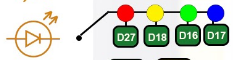
There are four leds on backside of the Magicbit with color red, yellow, green & blue. A LED(light-emitting diode) is a semiconductor light source that emits light when current flows through it. Blinking a LED is the hello world to the microcontroller programming world.
BUTTON
There are two buttons on the front of the Magicbit. The push-button is a component that connects two points in a circuit when you press it. The example turns on an LED when you press the button.
LDR
There is a LDR on the front of the Magicbit. LDR(Light Dependent Resistor) is a light-controlled variable resistor. The resistance of a photo-resistor decreases with increasing incident light intensity. You can measure light intensity using LDR as a analog output.
POTENTIOMETER
The potentiometer is a component with rotating contact that forms an adjustable voltage divider. A potentiometer is a simple knob that provides a variable resistance, which we can read into the Magicbit board as an analog value.
DISPLAY
OLED (Organic Light Emitting Diodes) is a flat light emitting technology. OLED display has a film of organic compound that emits light in response to an electric current.You can display varoius graphics and text on the display.
BUZZER
There is a buzzer on the front of the Magicbit. Buzzer is an electronic device commonly used to produce sound.
BATTERY
There is a Battery connector on the front of the Magicbit.Single cell rechargeable li-ion battery (3.7V) can be plugged in to a battery connector to puwer the Magicbit. Battery can be recharged by providing USb power to the Magicbit.
MODULES
There are four module connectors on the edge connector of the Magicbit, which we refer to as ports. Which can connect various accessories to Magicbit board and program to work with Magicbit. Matching accessory pin connector color marked on the Magicbit. As an example module with blue pin connector should plug in to blue port of the Magicbit.
USB
There is a micro USB port on the back of the Magicbit.Connect the micro USB port to a mobile phone charger or computer through a cable and it will draw power required for the board to function and it also used program magibit and data transferring with a computer.
WiFi
WiFi is a technology that uses radio waves to provide network connectivity. Magicbit consists with wifi module. WiFi technology has widely spread lately and you can get connected almost anywhere; at home, at work, in libraries, schools, airports, hotels and even in some restaurants enabling IOT connectivity capabilities.
BLUETOOTH
Bluetooth is a wireless technology standard used for exchanging data between fixed and mobile devices over short distances using short-wavelength UHF radio waves. Magicbit consists with wifi module which enables IOT connectivity capabilities
EXPANSION HEADER
Magicbit can connect various electronic sensors, electronically controlled actuators,etc to Magicbit via these external connectors
CROCODILE CLIP
Magicbit crocodile clip connectors used to connect an electrical cable to a battery or some other component. Functioning much like a spring-loaded clothespin, the clip’s tapered, serrated jaws are forced together by a spring to grip an object
RESET BUTTON
In electronics and technology, a reset button is a button that can reset a device. On Magicbit, the reset button restarts the Magicbit’s programme
Getting Started

The open-source Arduino Software (IDE) makes it easy to write code and upload it to the board. It runs on Windows, Mac OS X, and Linux. The environment is written in Java and based on Processing and other open-source software. Learn more about Arduino
Magicbit is based on ESP32 and Arduino core for the Magicbit forked from the espressif/arduino-esp32
Installation Instructions
- Relase Link -https://github.com/Magicbitlk/arduino-esp32/releases/download/V1.0.0/package_Magicbit_index.json
- Install the current upstream Arduino IDE at the 1.8 level or later. The current version is at the [Arduino website](http://www.arduino.cc/en/main/software).
- Start Arduino and open Preferences window.
- Enter one of the release links above into Additional Board Manager URLs field. You can add multiple URLs, separating them with commas.
- Open Boards Manager from Tools > Board menu and install Magicbit platform (and don’t forget to - - select Magicbit from Tools > Board menu after installation).

Powering Up
Magicbit can be powerup by either connecting USB cable or connecting battery. For programming USB cable must be connected to the computer. For the first time powering up Magicbit self test program will be running on the Magicbit and you can see the features available and functional tests on Magicbit display.
To check whether drivers are correctly installed open the Ardunio IDE and go the Tools menu. There should be a port (Eg:COM1) shown when plugging Magicbit to the computer as shown below. If not please follow Installation drivers section.

Installation Drivers (Optional)
Magicbit has CH340 chip as USB-Serial converter which driver already packaged with Ardunio IDE. If port not shown in the Arduino as shown below please install driver
First Project
- Open Ardunio IDE if not opened already.
- Select Magicbit from Tools->Boards
- Select port Tools->Ports
- Open Blink Example File->Examples->Basic->Blink
- Upload the code to the Magicbit using upload button on Arduino IDE
- If Green Led on backside of the Magicbit is blinking your have just begun the magic with Magicbit
Warning
To use analogWrite, Tone and Servo funtions,Include ESP32Servo Sketch->Include Library->ESP32Servo or put #include <ESP32Servo.h> on top of arduino sketch.
Getting Started
Example 1: Blinking an LED
Introduction
In this example you are learning how to turn on and off a LED or any other actuator which can be controlled by a digital output such as relay, bulb, motor.
Learning Outcomes
- Digital Write
- Delay Functions
Components
- Magicbit
Theory
A digital output allows you to control a voltage with an electronic device. If the device instructs the output to be high, the output will produce a voltage (generally about 5 or 3.3 volts). If the device instructs the output to be low, it is connected to ground and produces no voltage.Here Magicbit is the device and output voltage is either 3.3V for HIGH and 0V for LOW.
Methodology
Magicbit equipped with four onboard leds in Magicbit development board, Lets select yellow LED (which is wired to D18)
By setting output state to high of LED pin will turn on the led and by setting output state to LOW will turn of LED.
Coding
void setup(){
   pinMode(18,OUTPUT);
}
void loop(){
   digitalWrite(18,HIGH);
   delay(1000);
   digitalWrite(18,LOW);
   delay(1000);
}
Explanation
pinMode(pin, Mode): Configures the specified pin to behave either as an input or an output. Here we use pin as an output
digitalWrite(pin No, State): Write a HIGH or a LOW value to a digital pin.Pin mode must be setup for the same pin in Setup to work this function properly.
delay(ms): Pauses the program for the amount of time (in milliseconds) specified as parameter.(note 1000 milliseconds equals to one second)
Note
Write code for a knight rider pattern using on board leds of Magicbit
Example 2: Reading the state of a push button
In this example you are learning how read a digital input from something like a button & use it to turn on and off a LED or any other digital device.
From this example, you’ll get an understanding about,
- Digital Read
- IF-ELSE conditions
- Variables
- Magicbit
A digital input allows you to read digital signals. Microcontroller recognizes the signal as 1(HIGH) when the signal is close to 3.3v (or 5v depending on the microcontroller) and recognizes as 0(LOW) when the signal is close to 0v. This reading can be used in the program to do various things.
Magicbit equipped with two onboard push buttons in Magicbit development board, Lets select the push button which is wired to D34. Buttons on the board are in pulled up internally (to learn more about pullups/pulldowns follow this link), which means when button is not pressed the status of the button is 1(HIGH), & when the button is pressed the status of the button is 0(LOW).
Also like in previous example we need to select an LED to indicate the change, lets select RED LED which is wired to pin D27.
First we set the input output configurations of the Button and the LED using pinMode, in this case button is an INPUT, LED is an OUTPUT. Then in the loop section we check the state of the button & store it in an int type variable called buttonState (follow this link to learn more about data types in arduino).
Then we can use the variable as the condition of the if block, and if the button is pressed, the bulb should turn on, and the button is not pressed the light should turn off.
void Setup(){
   pinMode(27,OUTPUT);
   pinMode(34,INPUT);
}
void loop(){

 int buttonState = digitalRead(34);
 if(buttonState == LOW){
   digitalWrite(27, HIGH);
 }else{
   digitalWrite(27, LOW);
 }
}
digitalRead(pin No): Reads the condition of the given pin and returns a digital value HIGH or LOW.
IF/ELSE: Used to evaluate a digital condition, we can put a digital logic condition in then parenthesis. If the condition is true, it executes the code block in the immediate curly bracket section, if the condition is false it executes the code block in the else curly bracket.
- if(condition){
- //Do if condition is true
- }else{
- //Do if condition is false
}
Note
Write a code to toggle an LED in the button press. LED turns on when button pressed & released, LED turns off when button is pressed & released again. (Hint: Make use of variables to ‘remember’ the state of the button press).
Example 3: Working with Analog Write
Introduction
In this example you are learning how to turn on and off a LED or any other actuator which can be controlled by a digital output such as relay, bulb, motor.
Learning Outcomes
From this example, you’ll get an understanding about,
- Pulse Width Modulation
- Analog Write
Components
- Magicbit
Theory
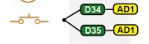
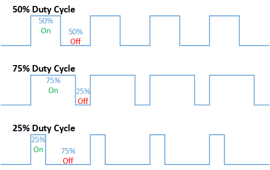
To change the brightness of a LED we could change the voltage the LED is supplied with, but in a microcontroller, ability to change the voltage (converting a digital number to an analog voltage) is limited, so a method called PWM (Pulse Width Modulation) is used. What this does is pulsing on and off the pin in a high frequency. The length of the pulses creates the perception of brightness.
Duty cycle is a term used to describe the ratio between on and off times.
In this example higher Duty cycle gives higher brightness & lower duty cycle gives lower brightness.
Methodology
Lets select green LED (which is wired to D16). We will use a for loop to generate the duty cycle (0 - 0% duty, 255-100% duty). And also to generate 255 cycles.
Coding
#include <ESP32Servo.h>

void setup(){
      pinMode(16,OUTPUT);
}
void loop(){
      for(int i = 0; i < 256; i++){
      analogRead(16, i);
      delay(10);
}
Explanation
for(int i=0; i<256; i++): There are 3 parameters in a for loop, first parameter we are defining a variable to store the value generated by the for loop. Second parameter specifies the condition that needs to be true to run the for loop(else it breaks out from the loop), third parameter specifies the change happens to the variable in each cycle, in this case 1, added to i.
analogWrite(pin number, pwm value): You can input the pin number you need to do pwm and then the pwm value you need to give to that pin. This assigns the corresponding duty cycle to the pin.
Note
This example we have coded to increase the brightness, write a code to do the opposite of that, to fade the brightness of the led, & put both effects together to create a beautiful fade & light up effect.
Example 4: Using Serial Protocol
Introduction
In this example you are learning to use serial communication function.
Learning Outcomes
From this example, you’ll get an understanding about,
- Serial Protocol usage between Magicbit & the PC
Components
- Magicbit
- Computer with arduino installed
Theory
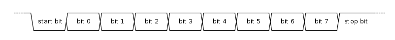
In microcontroller programming, communication between devices is essential. There are hundreds of protocols available, but most common & easy to use is Serial Protocol. Commonly used to communicate information between a microcontroller and a computer.
Methodology
We configure a button as the 2nd example (D34 is used). Then we initialize serial communication between the computer and Magicbit. After that in the loop section if condition check if the button is pressed. If pressed, it prints “Button Pressed” on the serial console.
You could use the serial monitor window of arduino IDE to view the serial output
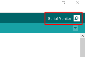
Then the serial console appears (you have to select the serial port number correctly, follow this link to learn how to).
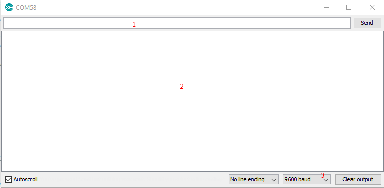
1: You can type in stuff here & hit enter to send data to Magicbit
2: This area shows the data coming from Magicbit
3: From this menu you have to select a common baudrate between the computer and the magic bit.
Coding
void setup(){
  pinMode(34,INPUT);
  Serial.begin(9600);
}
void loop(){
  if(digitalRead(34) == LOW){
    Serial.println(“Button is Pressed”);
  }
}
Explanation
Serial.begin(baudrate): Initializes a serial connection, baudrate specifies the speed of data transfer (bits per second). Standard values are 1200, 2400, 4800, 9600, 14400, 19200, 38400, 57600, 115200, 128000 and 25600
Serial.print(stuff to print): Using this function, serial data can be sent, stuff to print can be any type of arduino variable, or even a static string.
Serial.println(stuff to print): Using this function, serial data can be sent, stuff to print can be any type of arduino variable, or even a static string, this is different than Serial.print() is this always prints the content in a new line, rather than printing all in one line.
Activity
Note
do the same example using Serial.print(), observe the difference. Create a button press counter, which displays the button press count on the serial console of arduino IDE.
Example 5: Reading an Analog Signal
Introduction
In this example you are learning to read an analog sensor & print it on the serial console.
Components
- Magicbit
Theory
In real world most of the signals we encounter are analog signals (temperature, air pressure, velocity), they are continuous. But computers work on digital domain, to interact between the worlds, representing an analog signal in the digital domain is important. (to read more about analog to digital conversation, follow this link)
Methodology
For this example we use the potentiometer on the Magicbit board, which is connected to pin, D39. It generates a voltage between 0 and 3.3V according to the angle of the potentiometer.
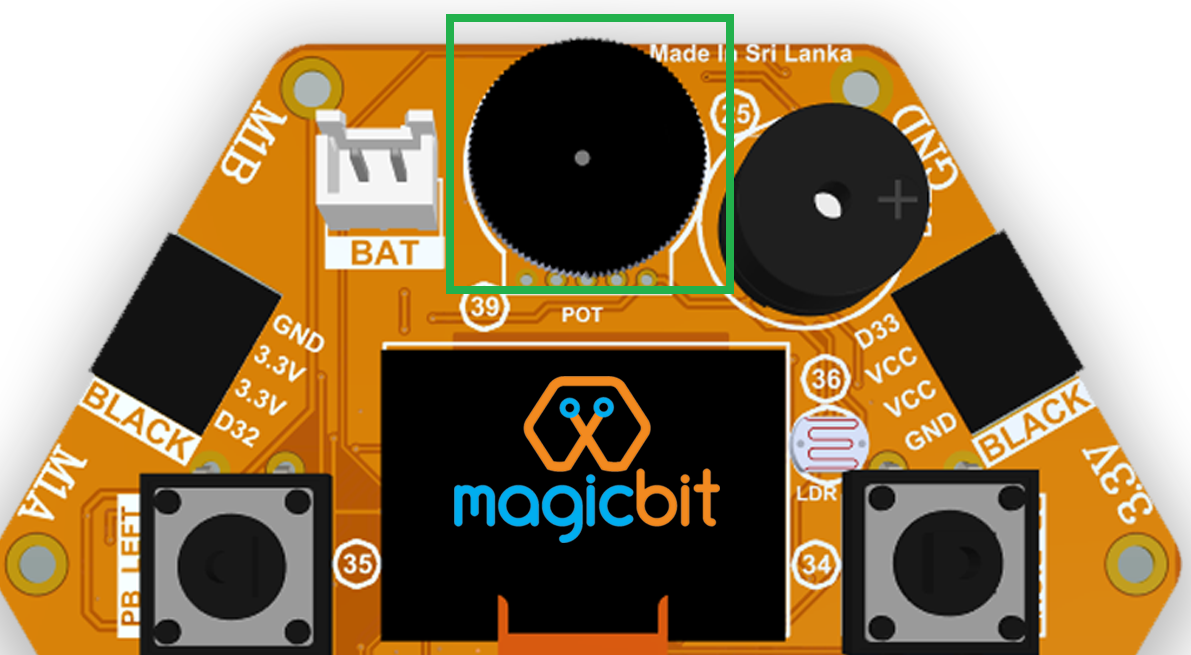
We read the analog signal and storing it in an int type variable(0v= 0 analog value, 3.3v = 1024 analog value), sensorValue, later, we use this value to print on the serial window of arduino IDE as well as light up the red LED(D27) if the analog value exceeds than 512.
Coding
void setup(){
     pinMode(39,INPUT);
     pinMode(27,OUTPUT)
     Serial.begin(9600);
}
void loop(){
     int sensorValue = analogRead(39);
     Serial.println(sensorValue);

     if(sensorValue > 512){
        digitalWrite(27,HIGH);
     }else{
        digitalWrite(27,LOW);
     }
 }
Explanation
analogRead(pin No): this reads and assigns the corresponding analog value to the left.
Activity
Note
Do the same example using the LDR on the board (D36)
Example 6: Generating Tones
In this example you are learning to generate a tone using the onboard buzzer on the Magicbit.
Components
- Magicbit
Theory
Piezo buzzers are commonly used in embedded systems to give audible tones. Combined with ESPservo library Magicbit can generate various tones. (Follow this link to know how to install ESPservo library)
Methodology
For this example we use the piezo buzzer wired to pin 25 of the Magicbit.

ESP32Servo.h library is used to generate pwm signals needed to generate tones. We could specify the frequency & duration of the tone.
Coding
#include <ESP32Servo.h>
void Setup(){
   pinMode(25,OUTPUT);
}
void loop(){
   tone( 25 ,4186,500); //C Note
   delay(1000);
   tone( 25,5274,500); //E Note
   delay(1000);
}
Explanation
tone(pin No, frequency, duration): generates pwm to corresponding to the given parameters
Activity
Note
Create a program that plays one frequency when one push button on the board pressed, and another frequency when the other push button when pressed.
Example 7: Using the onboard OLED Screen
Introduction
Color OLED screen on Magicbit can display text as well as simple logos & images.
Learning Outcomes
From this example, you’ll get an understanding about,
- Using Adafruit OLED library
Components
- Magicbit
Theory
Magicbit has a 0.96” OLED Screen which can be communicated with from I2C protocol. The display has the address, 0x3c.
Methodology
Adafruit OLED library(Adafruit_SSD1306 & Adafruit_GFX) is used to handle the LCD, its important to install those libraries beforehand. First we create the content we need to print onto the screen and then use display.display command to update the screen.
Coding
#include <Wire.h>
#include <Adafruit_GFX.h>
#include <Adafruit_SSD1306.h>
#define OLED_RESET 4

Adafruit_SSD1306 display(128,64);

void setup(){
  display.begin(SSD1306_SWITCHCAPVCC, 0x3C);
  display.display();
  delay(3000);
}


void loop(){
  display.clearDisplay();
  display.setTextSize(2);
  display.setTextColor(WHITE);
  display.setCursor(10, 0);
  display.println("Hello");

  display.setTextColor(WHITE);
  display.setTextSize(1);
  display.setCursor(0, 25);
  display.println("Welcome to");
  display.println();
  display.println("Magic");
  display.println("Bit");
  display.display();
  display.clearDisplay();

  delay(1000);

  }
Explanation
display.clearDisplay(): Clears the OLED display.
display.setTextSize(2): Set the font size of the text.
display.setCursor(0, 25): Sets the cursor(determines where the next text will appear).
display.println(stuff to print): print the data given on a new line, similar effect like Serial.println.
display.setTextColor(WHITE): Sets the color of the text.
display.display(): Updates the changes to the screen.
Note
Make a program to display the ADC value of the potentiometer on the OLED display.